


Our Story


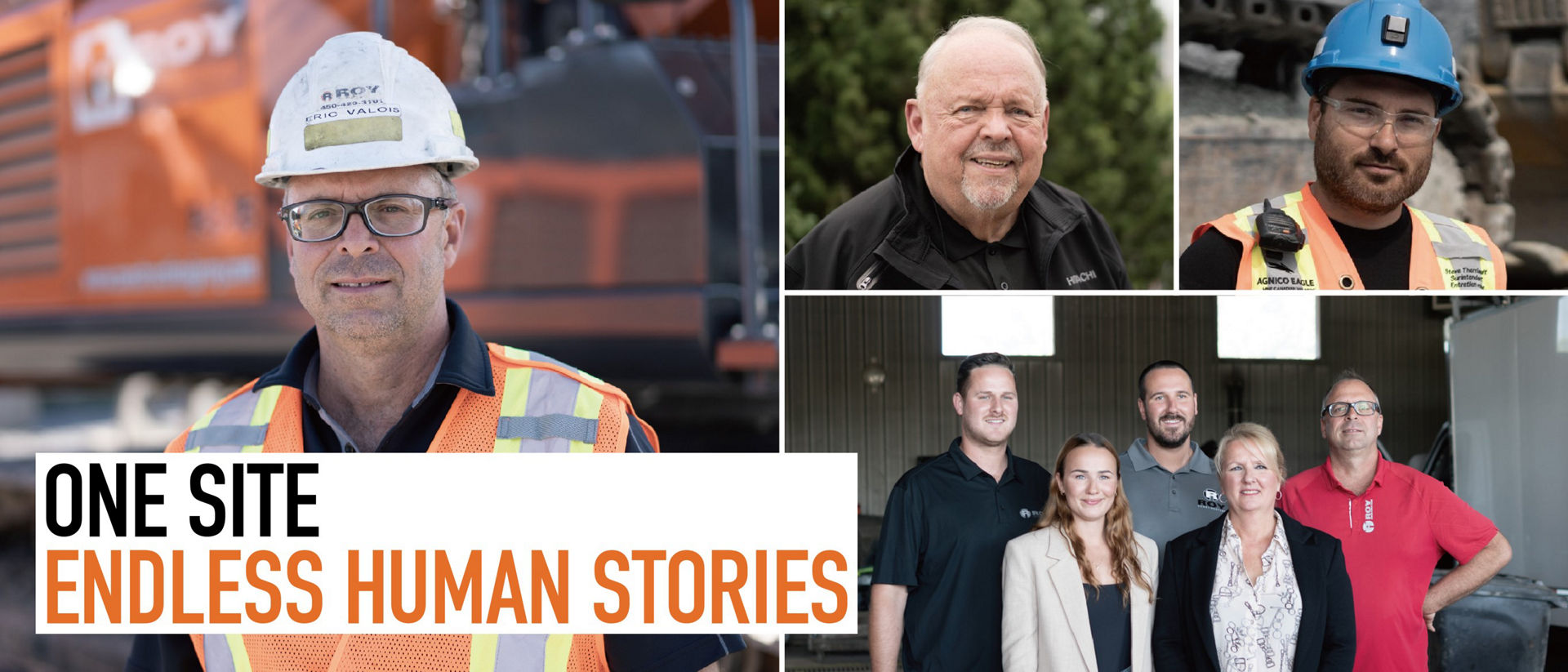
To pass on a productive environment and prosperous cities to future generations.
Hitachi Construction Machinery has been developing its engineering capabilities in line with social development and manufacturing and advancing construction machinery, which supports the construction of social infrastructure, industry and residential houses around the world.
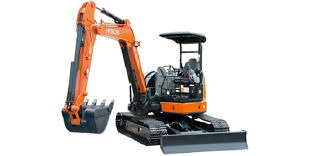
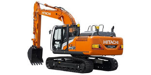
Products and Solutions
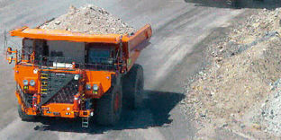
- Products
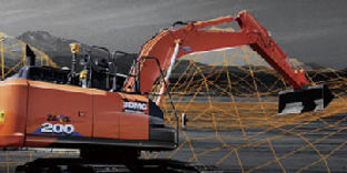
- Solutions
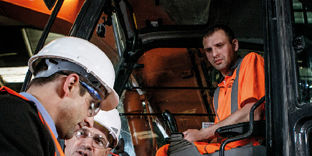
- Parts and Service
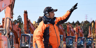
- Rental and Used


Press Releases
-
24th April 2024
-
24th April 2024
-
24th April 2024
Topics
-
18th April 2024
-
5th March 2024
-
28th February 2024
Important Notice
-
10th April 2023
-
13th June 2022
-
4th March 2022


